Walpersdorfer Str. 38
91126 Schwabach
Tel.:
+49 (0)9122 - 63148-0
Fax.:
+49 (0)9122 - 63148-29


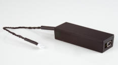
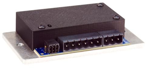
SFU 400pro


USB Adapter (optional)

Technische Daten Technical specifications
SFU400pro
Versorgungsspannung
Power Supply
Anschluss / connection: X1 Steckschraubklemmen für Litzen oder Drähte bis
/ plugable screw terminals for strands or wires up to 3 mm²
24 V…48 V DC (+10 %) / 15 A mit PE Anschluss an / with PE connection at X1
Kein Verpolschutz / No protection against faults due to reversed polarity
Sicherungen
Fuses
FS1: intern 20AT/63V SMD
empfohlene externe Absicherung / recommended external fusing: 18AT
Ausgangsleistung
Output Power
750VA / S1 – 100 %
850VA Peak
Spindelanschluss
Spindle Connection
Anschluss / connection: X2 Steckschraubklemmen für Litzen oder Drähte bis
/ spring clamps for strands or wires up to 3 mm²
6-pol.: U, V, W, PE, GND, PTC Anschluss an / connection
PTC, KTY, PT1000 Temperatursensor Spindel, Schaltschwelle einstellbar / temperature
sensor adjustable
Ausgangsspannung
Output Voltage
max. 32 V AC
Ausgangsstrom
Output Current
Phasendauerstrom / phasen current 15 A (18A Peak)
Bremschopper
Brake Chopper Resistor
integriert / on board 54 Ω / 4 W / Einsatzspannung / threshold voltage: 54 V
Ausgangsfrequenz
Output Frequency
AC: 1.666 Hz / max. 100.000 Upm rpm @ 2pol Spindle
Steuereingänge
Control inputs
Anschluss / connection: X3 – Push-in Anschluss für Litzen oder Drähte bis
/ Push-in spring connection for strands or wires up to 0,5 mm²
Digital In: Start / Stop ( 0 / 24 V ) "0" = 0…5 V, "1" = 13…24 V
zulässiger Spannungsbereich / permissable voltage range -3 V…30 V DC
Imax @ 24 V = 10 mA
Analog In: Drehzahl Sollwertvorgabe / duty value rotational speed ( 0…10 V ) Min-Max
Rin: 60 kΩ, 10 bit
Steuerausgänge
Control outputs
Anschluss / connection: X3 – Schraubklemmen für Litzen oder Drähte bis
/ screw terminals for strands or wires up to 0,5 mm²
2 x Digital Out: Open Collector; 45 V/0,5 A nicht kurzschlussgeschützt
no short circuit protection
induktive Lasten müssen mit externen Dioden abgesichert werden
inductive loads must be protected externally by diodes
Schnittstellen Interface
Anschluss/ connection: X4 RS232, 115 kBd
Betriebsanzeigen
Operating status indicators
2 x LEDs grün / rot, 2 x LEDs green / red
Statusanzeige in verschieden Blinkcodes / status display with different blink codes
max. Maße B x H x T (mm)
max. dimensions W x H x D (mm)
73 x 53 x 14 mm, auf Montageplatte / on mounting plate 100 mm x 55 mm x 22 mm
Gewicht
Weight
120 g
Betriebsbedingungen
Operating conditions
5 °C – 40 °C / no condensation
Für Dauerbetrieb größer 12Aout ist für eine Wärmeabfuhr der Montageplatte zu sorgen.
For continuous operation greater than 12Aout, heat dissipation from the mounting plate
must be ensured.


SFU 400pro
Technische Daten Technical specifications
SFU400pro
Versorgungsspannung
Power Supply
Anschluss / connection: X1 Steckschraubklemmen für Litzen oder Drähte bis
/ plugable screw terminals for strands or wires up to 3 mm²
24 V…48 V DC (+10 %) / 15 A mit PE Anschluss an / with PE connection at X1
Kein Verpolschutz / No protection against faults due to reversed polarity
Sicherungen
Fuses
FS1: intern 20AT/63V SMD
empfohlene externe Absicherung / recommended external fusing: 18AT
Ausgangsleistung
Output Power
750VA / S1 – 100 %
850VA Peak
Spindelanschluss
Spindle Connection
Anschluss / connection: X2 Steckschraubklemmen für Litzen oder Drähte bis
/ spring clamps for strands or wires up to 3 mm²
6-pol.: U, V, W, PE, GND, PTC Anschluss an / connection
PTC, KTY, PT1000 Temperatursensor Spindel, Schaltschwelle einstellbar / temperature
sensor adjustable
Ausgangsspannung
Output Voltage
max. 32 V AC
Ausgangsstrom
Output Current
Phasendauerstrom / phasen current 15 A (18A Peak)
Bremschopper
Brake Chopper Resistor
integriert / on board 54 Ω / 4 W / Einsatzspannung / threshold voltage: 54 V
Ausgangsfrequenz
Output Frequency
AC: 1.666 Hz / max. 100.000 Upm rpm @ 2pol Spindle
Steuereingänge
Control inputs
Anschluss / connection: X3 – Push-in Anschluss für Litzen oder Drähte bis
/ Push-in spring connection for strands or wires up to 0,5 mm²
Digital In: Start / Stop ( 0 / 24 V ) "0" = 0…5 V, "1" = 13…24 V
zulässiger Spannungsbereich / permissable voltage range -3 V…30 V DC
Imax @ 24 V = 10 mA
Analog In: Drehzahl Sollwertvorgabe / duty value rotational speed ( 0…10 V ) Min-Max
Rin: 60 kΩ, 10 bit
Steuerausgänge
Control outputs
Anschluss / connection: X3 – Schraubklemmen für Litzen oder Drähte bis
/ screw terminals for strands or wires up to 0,5 mm²
2 x Digital Out: Open Collector; 45 V/0,5 A nicht kurzschlussgeschützt
no short circuit protection
induktive Lasten müssen mit externen Dioden abgesichert werden
inductive loads must be protected externally by diodes
Schnittstellen Interface
Anschluss/ connection: X4 RS232, 115 kBd
Betriebsanzeigen
Operating status indicators
2 x LEDs grün / rot, 2 x LEDs green / red
Statusanzeige in verschieden Blinkcodes / status display with different blink codes
max. Maße B x H x T (mm)
max. dimensions W x H x D (mm)
73 x 53 x 14 mm, auf Montageplatte / on mounting plate 100 mm x 55 mm x 22 mm
Gewicht
Weight
120 g
Betriebsbedingungen
Operating conditions
5 °C – 40 °C / no condensation
Für Dauerbetrieb größer 12Aout ist für eine Wärmeabfuhr der Montageplatte zu sorgen.
For continuous operation greater than 12Aout, heat dissipation from the mounting plate
must be ensured.


![[x]](index_htm_files/close.png "Schließen")

